In March 2018 I started out my ergonomic keyboard journey with an Ergodox EZ. There are many good things which can be said about the Ergodox EZ. It is a very reliable keyboard. It’s super easy to customize using the EZs web-based editor and updating it with teensy works great.
The reason I started looking at alternative keyboards was because my hands are a little too small to use it efficiently. When I want to use the thumb cluster my fingers move off the home row which significantly reduces my typing speed. The same is true for the outer most keys on either side.
I started out searching for smaller ergnomic split keyboards. After buying and assembling a number of split keyboards kits like the Ergotravel, Redox, SOL or crkbd I gave up searching as no keyboard was what I was looking for.
The crkbd is the closest with its small form factor and numerous gimmicks. Using it however is a constant fight over the space constraint pro micro which restricts which QMK features you can enable and the small but noticable lag when typing fast.
So in late December 2018 I decided to build my own keyboard.
The feature set was small enough: I wanted the reliability of the Ergodox EZ with the form factor and feature set of the crkbd. Today I’m writing this blog post on the revision 0.3 of what I call the kepler keyboard.
Revision 0.3 has the following hardware:
- flippable PCB
- single ARM MCU: STM32F303CCT6
- PCA9675 i/o expander
- PCA9617A i2c buffer
- SSD1306 oled display on the left side
- hot swappable mx switches
As you can see from the listing kepler a single MCU keyboard. The MCU is located on the left hand side. All communication between the sides uses an I2C bus running at 1Mhz:
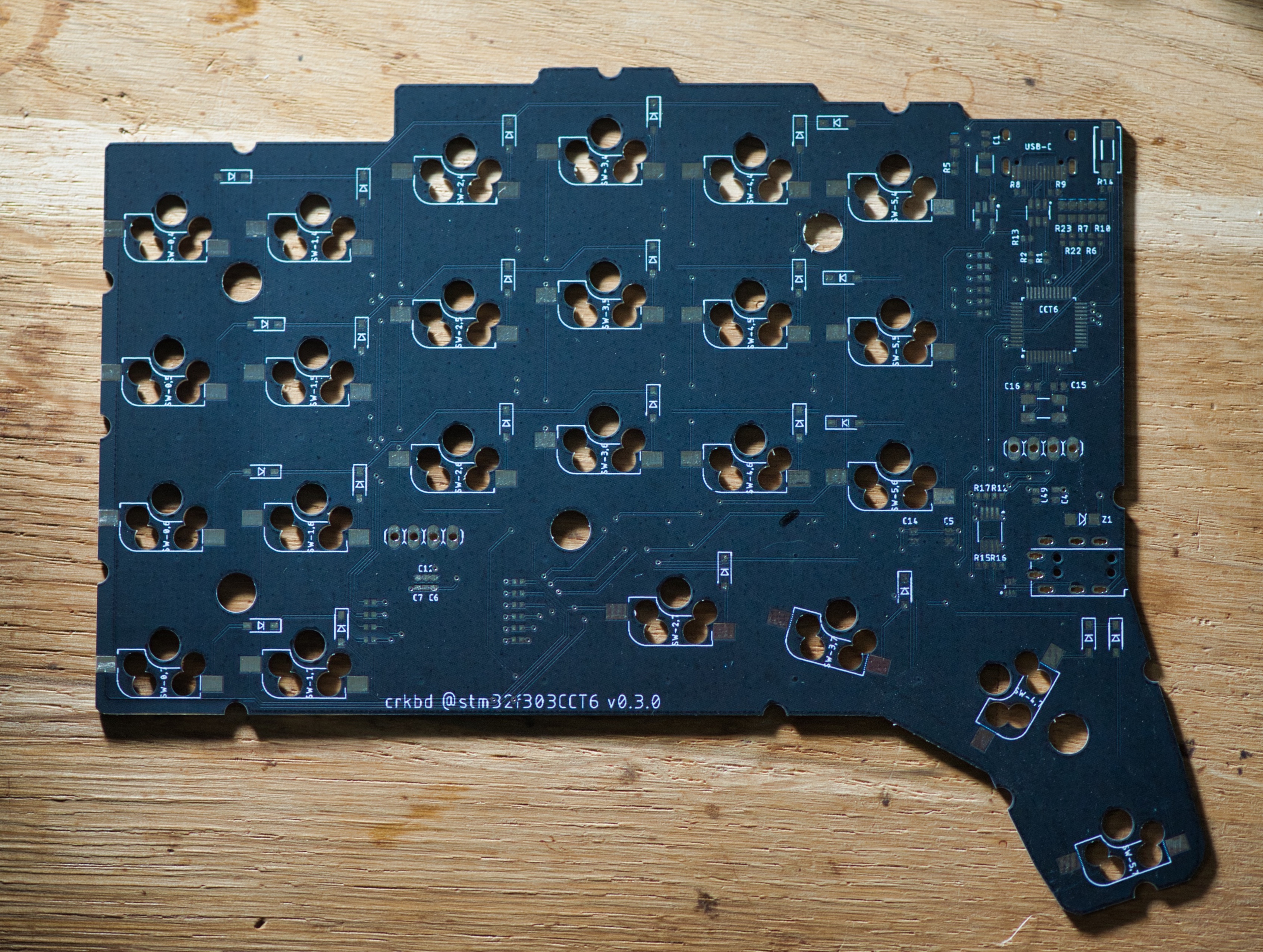
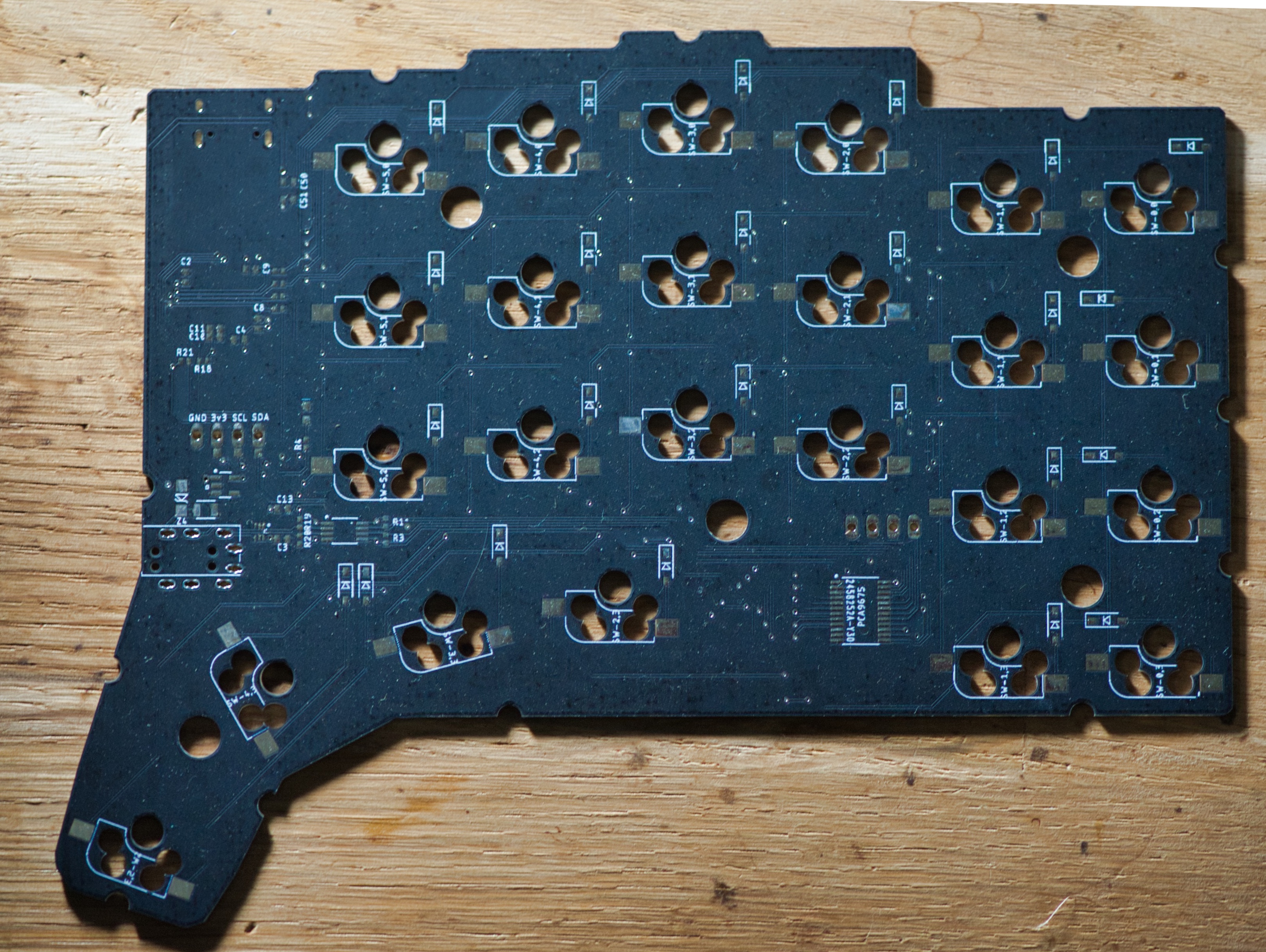
Kepler has three more keys than the crkbd: it features an extended thumb cluster, as well as additional keys at the outer sides: altogether 48 keys, 24 per side.
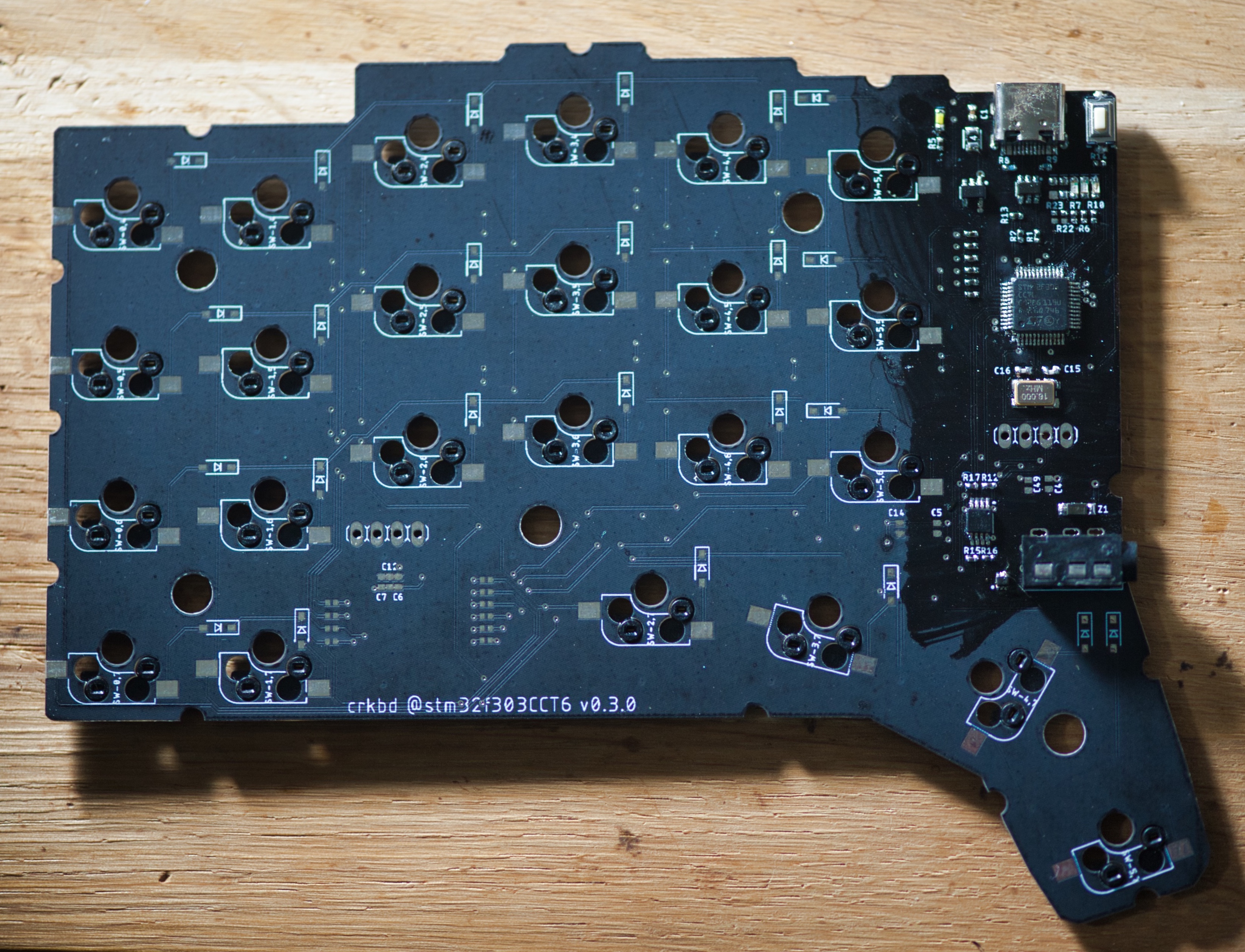
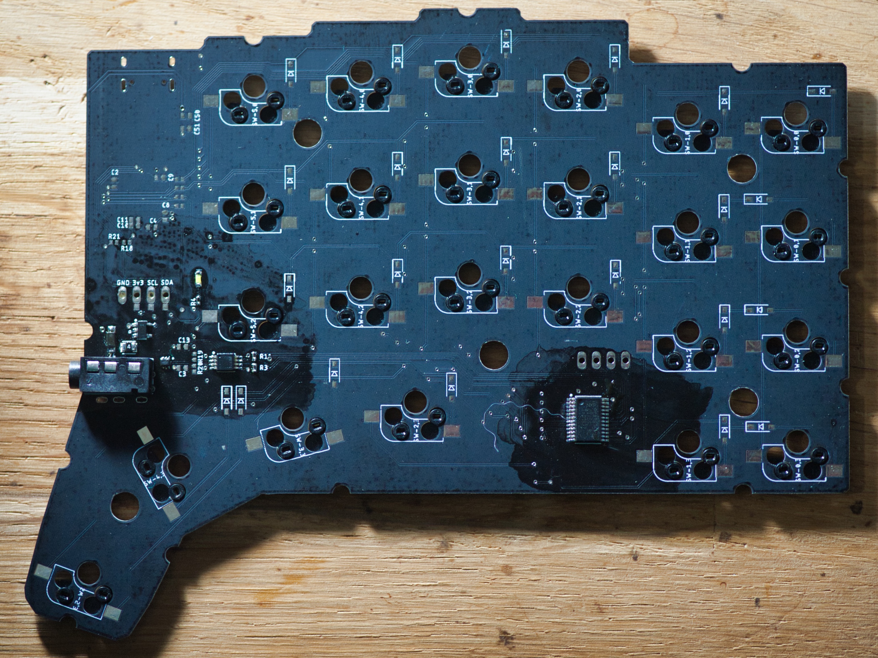
To ensure the smoothest typing experience the oled display is moved to the second I2C bus on the STM32F303. Also I opted to use 0402 components for all capacitors and resistors, mostly for aesthetic reasons.
Now getting to this point was a journey which thought me a lot, and I plan on writing on that separately. At the moment I’m just happy that after nearly 6 months of work this project is finally ready to be shown.
However, it’s still far from complete. It’s missing the RGB lights, which will be added to the fourth revison using the IS31FL3733. Lastly I’m also working on a case design for it which can be CNC’d to add a professional look.
I’ll follow up with details once I have something to show for.
Stay tuned for more blog posts related to electronics and keyboard prototyping specifically :)